5100-XX-IT

Electrochemical Toxic Gas Sensor Module 5100-XX-IT

Electrochemical Toxic Gas Sensor Module 5100-XX-IT

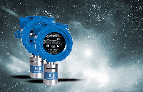
Sierra Monitor’s fixed 5100-XX-IT gas module monitors toxic gases such as Hydrogen Sulfide (H2S), Carbon Monoxide (CO), Nitrogen Dioxide (NO2), Ammonia (NH3), Oxygen (O2) Deficiency, and others.

The 5100-XX-IT module is based on electrochemical technology, a proven, less-expensive option that offers high accuracy, low power requirements, and sensitivity to a particular gas in the parts-per-million range.

The proven 5100-XX-IT fixed gas sensor module requires calibration only every six months, cutting operating costs and time. As part of the Sentry IT “smart” detector line, the module can be remotely diagnosed and calibrated via Remote Sensor Capability, a valuable asset for toxic gas monitoring. The 5100-XX-IT also offers a three or four wire 4-20mA analog output signal. By integration of IT modules into a Sentry system, the user gains the capability of system Modbus serial communications, extensive diagnostics features, WebServer interface, multiplexed sensor wiring, and field-proven reliability.

The Electrochemical Toxic Gas Sensor Module 5100-XX-IT is approved and certified by a variety of third party agencies, including FM, CE, CSA, SIL-2, ATEX, and IECEx. These approvals and certifications assure our customers that we carry only the highest quality of products and performance.

GlobalCal™

The 5100-XX-IT supports GlobalCal™, our unique global calibration feature of the Sentry IT Controller. This allows a single technician to calibrate connected detectors from the Sentry IT Controller. With GlobalCal, the calibration happens at the controller level. Multiple sensors can be connected to a single controller, allowing groups of sensors to be calibrated at the same time. Standard gas is applied remotely, using permanently installed tubing, rather than direct delivery to the fixed gas detector.

Combined with the six-month calibration interval, GlobalCal reduces labor costs associated with calibration. The need to shut down active process areas for calibration consequently costs facilities thousands of dollars in lost production time. GlobalCal, with its remote and non-intrusive methods, allows production to continue during the calibration process, thus avoiding the costs of lost production. In addition, factory-authorized service technicians performing gas detector calibration save time and costs by remotely calibrating all gas detectors at once from the Sentry IT Controller.

Integral LED Display

Easily calibrate and access gas concentrations, relay statuses, and diagnostics

Internal Continuous Self-Diagnostics

Automatically indicate any fault or optics problems

Menu-Driven System

Rapidly adjust user-friendly configuration of alarm setpoints, calibration, maintenance, and alarm acknowledgment

MODBUS RTU Interface

Provide an easy interface to the world’s most common industrial protocol interface

FM-Approved 6 Month Calibration Interval

Dramatically reduce maintenance time and half the costs as found on others for the user

SMC Sentry Digital Bus Interface

Connect easily with existing Sentry systems that have been in operation for many years

GlobalCalTM support

Non-intrusively calibrate all connected sensors at the same time without declassifying the area

Optional Remote Sensor Configuration

Access the controller over a remote network for convenience or for hard-to-access areas

Optically Isolated 4-20 mA Output

Interface effortlessly with common factory communication links and provide flexibility for the output

HART Interface

Effortlessly communicate over legacy 4-20 mA analog instrumentation wiring

Gas Type Model Std.Range(1) Opt. Max Range Resolution Response Time (2) Accuracy
Operating Range
°F °C RH*
Oxygen (O2) 5100-03-IT 5-25 % Vol 25% Vol 0.1% <10 sec. +/- 0.2%
-4 to 122 -20 to 50 15 – 99%
Carbon Monoxide (CO) 5100-04-IT 0-500PPM 1200 PPM 0.5 PPM <35 sec. +/- 1PPM
-4 to 122 -20 to 50 15 – 99%
Hydrogen Sulfide (H2S) 5100-05-IT 0-100PPM 100 PPM 0.1 PPM <35 sec. +/- 1PPM
-4 to 122 -20 to 50 15 – 99%
Chlorine (Cl2) 5100-06-IT 0-10PPM 10.0 PPM 0.1 PPM <60 sec. +/- 1PPM
-4 to 122 -20 to 50 15 – 99%
Chlorine Dioxide (ClO2) 5100-08-IT 0-3PPM 3.0 PPM 0.1 PPM <60 sec. +/- 1PPM
-4 to 122 -20 to 50 15 – 99%
Sulfur Dioxide (SO2) 5100-10-IT 0-100PPM 100 PPM 0.5 PPM <20 sec. +/- 1PPM
-4 to 122 -20 to 50 15 – 99%
Nitrogen Dioxide (NO2) 5100-12-IT 0-20PPM 20.0 PPM 0.2 PPM <35 sec. +/- 1PPM
-4 to 122 -20 to 50 15 – 99%
Hydrogen Dioxide (H2O2) 5100-21-IT 0-20PPM 20.0 PPM 0.1 PPM <100 sec. +/- 1PPM
-4 to 122 -20 to 50 15 – 99%
Ammonia (NH3) 5100-25-IT 0-100PPM 100 PPM 1.0 PPM <30sec. +/- 1PPM
-4 to 122 -20 to 50 15 – 99%
Hydrogen Fluoride (HF) 5100-26-IT 0-10PPM 10 PPM 0.5 PPM <30 sec. +/- 1PPM
-4 to 122 -20 to 50 15 – 99%
Ethylene Oxide (ETO) 5100-27-IT 0-20PPM 0-20PPM 0.1 PPM <90 sec. +/- 1PPM
-4 to 122 -20 to 50 15 – 99%
1. Optional ranges available *= Non-Condensing
2. Response time to 90% full signal value for applied concentration
Sensor Type Electrochemical
Performance Range:

  • Default range as above
  • User selectable alternative ranges Sensor Life: Typically >2 years

Sensor Life: Typically >2 years

Output Display: Fixed and scrolling LED

Signal Outputs:

  • Sentry digital bus
  • Analog 4-20mA
    • 3-wire non-isolated
    • 4-wire isolated
  • Serial RS-485 Modbus RTU

Relay: Optional

Options Relays:

  • 5 amp Alarm, Warning (0.25 amp Trouble)
  • 5A @ 250 VAC, 5A @ 30 VDC (Alarm, Warning)
  • Board includes auxiliary connection for Sentry multiplexing

HART: Termination board includes HART, MODBUS RS-485, 4-20mA, Digital Input, 2A Relay output, no Sentry bus

Power Power consumption: 2 watts maximum

Input voltage: 24 VDC nominal: 10-30 VDC

Remote Sensor Option 5100-03-IT: 10 feet

5100-04-IT: 15 feet

5100-05-IT: 15 feet

Built-in-Test (BIT) Manual and Automatic
Construction Dimensions: (H x W x D) (differs for 5100-25-IT & 5100-26-IT)

  • A1 & A2: 7.9 x 5.7 x 3.9 in. (20.1 x 14.5 x 9.9 cm)
  • S1 & S2: 7.6 x 4.4 x 4.9 in. (19.3 x 11.2 x 12.4 cm)

Weight:

  • A1 & A2: 3.4 lb. (1.5 Kg)
  • S1 & S2: 7.2 lb. (3.3 Kg)

Housing: Epoxy-coated, die-cast, copper-free aluminum or 316 stainless steel

Rating:

  • Explosion proof, Class 1, Div. 1, Groups B, C, D
  • Group IIB + H2 IP66, IP65, NEMA 4X

Warranty: 2 years

Approvals FM, CSA: For enclosure in hazardous locations

FM Performance Approval (5100-05-IT)

SIL-2 Certified (5100-04-IT, -05, -06-IT)

ATEX Certified II 2 G Ex d IIB+H2 T6 Gb

  • Ta = -20oC to 50oC (5100-05-IT)

IECEx Certified (5100-05-IT)

CE Mark (5100-05-IT)

ABS (5100-05-IT)

CQST Certified for China (5100-03, -04, -05-IT)

CCOE/PESO Certified for India

How to calibrate Sentry IT Gas Sensors with GLobalCal

Sentry IT fire and Gas Detection Solutions

THLink – Industrial Ethernet

Outil de diagnostic : Industrial Ethernet, indépendant du contrôleurs

Le THLink Industrial Ethernet, permet le contrôle et le diagnostic des réseaux PROFINET, MODBUS TCP et ETHERNET/IP. Les données sont collectées sur un réseua de 254 noeuds et  rendent disponibles ses données via le logiciel  THSCOPE. le THLINK Industrial Ethernet est facile à utiliser et peut être intégré sans interférer avec une installation existante

csm_THLink_IE_D_EN_170101_311_fbdb7e6c27

THLink Industrial Ethernet for an independent Access to PROFINET, EtherNet/IP and Modbus TCP Networks

  • Controller-independent
  • Independent of configuration tools
  • Only one tool needed to monitor multiple IP subnetworks (up to 254 nodes, one or more controllers

THLink Industrial Ethernet has been designed for Installation without Interference with Plant Operation

  • Connection to free port in industrial network, also possible during operation of the plant
  • No need to install TAPs or use mirror ports
  • Highest security (separate accesses for control room level and plant level, no routing)
  • Easy integration into existing plants thanks to compact design

Powerful Data Collection Capabilities Optimized for Ethernet-Based Industrial Communication

  • Support of the PROFINET, EtherNet/IP and Modbus TCP protocols
  • Collection also from standard Ethernet devices (e.g. PCs or camera systems)
  • PROFINET supervisor in PROFINET networks
  • Network load limit according to PROFINET guidelines

Optimized for Use by Maintenance Engineers, thanks to the THLink industrial Ethernet

  • Suitable for network acceptance testing, continuous monitoring and troubleshooting
  • Easy and intuitive handling and operation
  • Fault identification with intelligent troubleshooting assistance
  • Seamless integration with TH SCOPE diagnostics software
Functionality
  • Network detection and data collection
  • Alarm notification in case of fault
  • Basic monitoring, configuration
  • Integrated web server
Input Voltage 24 VDC (18 VDC … 32 VDC)
Current consumption max. 180 mA
Current consumption relay contact max. 100 mA
Operating Temperature -40 °C … +75 °C
Relative Air Humidity 5 … 95 % (no condensation)
Ethernet Ports RJ-45 (10Base-T/100Base-TX)
Supported SD Cards See Release Notes
Mounting 35 mm DIN rail
Dimensions (HxWxD) 22.5 x 99 x 114.5 mm
Weight 120 g
Certifications CE
GDA-JY-003037 TH LINK Industrial Ethernet

Scope of Delivery

Hardware TH LINK Industrial Ethernet
Documentation Installation Manual, Release Note (by download)

Additional Products and Services

ATV-LRA-JY-003024 TH SCOPE (software key)
ATV-LRL-JY-003025 TH SCOPE (hardware key)
ATV-LRA-JY-003028 TH LINK PC Industrial Ethernet (software key)
ATV-LRL-JY-003029 TH LINK PC Industrial Ethernet (hardware key)
ATV-TRA-PN-TECH Training “PROFINET Technology”
ATV-TRA-PN-CERTENG Training “PROFINET Commissioning and Troubleshooting”

LANTECH- SFP 2.5Gbps

Module SFP : 850nm VCSEL, Duplex LC, 2.5GBase-X

ATV-8330-262
  • Distance: 0.3km
  • Temperature en utilisation normale: -10°C ~ 70°C
  • Temperature en utilisation extrême: -40°C ~ 85°C

Les modules SFP enfichables Lantech 2.5GBase-X Small Form Factor sont conformes aux spécifications actuelles du SFP Multi-Source Agreement (MSA). L’émetteur VCSEL 850nm haute performance et le récepteur PIN haute sensibilité offrent des performances supérieures pour les applications SONET/SDH jusqu’à 0,3 km de liaisons optiques sur fibre multimode.

Caractéristiques:

  • Conforme à la norme SFP MSA
  • Conforme à l’interface de surveillance diagnostique SFP8472.
  • Conforme à 2500Base-X
  • Plugable à chaud
  • Transmetteur laser VCSEL 850nm
  • Connecteur Duplex LC
  • Interface 2 fils pour la gestion et le moniteur de diagnostic
  • Alimentation simple +3.3V
  • Distance de transmission de 0,3 km par rapport à la fibre multimode
  • Conforme à la directive RoHS

Absolute Maximum Ratings

Parameter

Symbol

Min.

Max.

Unit

Note

Storage Temperature

TST

-40

+85

°C

Supply Voltage

Vcc

-0.5

4.0

V

Storage Relative Humidity

RH

5

95

%

Recommended Operating Conditions

Parameter

Symbol

Min.

Typ.

Max.

Unit

Note

Case Operating Temperature
(Standard model)

TOP

-10

70

°C

Case Operating Temperature
(-E model)

TOP

-40

85

°C

Supply Voltage

Vcc

+3.15

+3.3

+3.45

V

Supply Current

ICC

240

mA

Transmitter Electro-Optical Characteristics

Parameter

Symbol

Min.

Typ.

Max.

Unit

Note

Optical launch Power

PO

-9

-3

dBm

1

Center Wavelength

λC

830

850

870

nm

Spectral Width (RMS)

Δλ

0.85

nm

Optical Extinction Ratio

ER

3.5

dB

Rise/Fall Time (10%~90%)

Tr/Tf

0.16

ns

Optical Eye Mask

ITU-T G.957 STM-16

Differential Data Input Voltage

VDIFF

400

2000

mV

Transmit Disable Voltage

VDIS

2.0

Vcc

V

Transmit Enable Voltage

VEN

GND

GND+0.8

V

Notes: 1. The optical power is launched into a 50/125μm multi-mode fiber.

Receiver Electro-Optical Characteristics

Parameter

Symbol

Min.

Typ.

Max.

Unit

Note

Receiver Sensitivity

PINMIN

-16

dBm

1

Maximum Input Power

PINMAX

-3

dBm

1

Operating Center Wavelength

λC

770

870

nm

LOS De-Assert

LOSD

-16

dBm

LOS Assert

LOSA

-30

dBm

LOS Hysteresis

LOSVHY

0.5

dB

Differential Data Output Voltage

Vout, pp

500

1200

mV

Data Output Rise/Fall Time (10%~90%)

Tr/Tf

0.18

ns

Receiver LOS Signal Output Voltage-Low

LOSVL

GND

GND+0.5

V

Receiver LOS Signal Output Voltage-High

LOSVH

2.4

Vcc

V

Notes: 1. Measured with a PRBS 231-1 test pattern @ 2488Mbps BER < 10-10

Pin Assignment


Diagram of Host Board Connector Block Pin Numbers and Name

Pin Description

Pin

Name

Function / Description

1

VeeT

Transmitter Ground

2

TX_Fault

Transmitter Fault Indication (1)

3

TX_Disable

Transmission Disable – Module disables on high or open (2)

4

MOD-DEF(2)

Module Definition 2 – SDA: Serial Data Signal

5

MOD-DEF(1)

Module Definition 1 – SCL: Serial Clock Signal

6

MOD-DEF(0)

Module Definition 0 – LVTTL Low (3)

7

Rate Select

Not Connected – Open Circuit

8

LOS

Receiver Loss of Signal (4)

9

VeeR

Receiver Ground

10

VeeR

Receiver Ground

11

VeeR

Receiver Ground

12

RD-

Inverse Received Data out, Differential LVPECL, AC coupled

13

RD+

Received Data out, Differential LVPECL, AC coupled

14

VeeR

Receiver Ground

15

VccR

Receiver Power

16

VccT

Transmitter Power

17

VeeT

Transmitter Ground

18

TD+

Transmitter Data In, Differential LVPECL, AC coupled

19

TD-

Inverse Transmitter Data In, Differential LVPECL, AC coupled

20

VeeT

Transmitter Ground
Note1: TX Fault is open collector/drain output which should be pulled up externally with a 4.7K~ 10KΩ resistor on the host board to supply <VccT+0.3V or VccR+0.3V. When high, this output indicates a laser fault of some kind. Low indicates normal operation. In the low state, the output will be pulled to <0.8V.
Note2: TX Disable input is used to shut down the laser output per the state table below. It is pulled up within the module with a 4.7K~10KΩ resistor. 1)Low(0~0.8V): Transmitter on; 2)Between(0.8V and 2V): Undefined; 3)High (2.0~ VccT): Transmitter Disabled; 4)Open: Transmitter Disabled
Note3: Mod-DEF 0, 1, 2. These are the module definition pins. They should be pulled up with a 4.7K~10KΩ resistor on the host board to supply less than VccT+0.3V or VccR+0.3V. Mod-DEF(0) is grounded by the module to indicate that the module is present. Mod-DEF(1) is clock line of two wire serial interface for optional serial ID. Mod-DEF(2) is data line of two wire serial interface for optional serial ID.
Note4: LOS (Loss of signal) is an open collector/drain output which should be pulled up externally with a 4.7K~10KΩ resistor on the host board to supply <VccT+0.3V or VccR+0.3V. When high, this output indicates the received optical power is below the worst case receiver sensitivity (as defined by the standard in use). Low indicates normal operation. In the low state, the output will be pulled to <0.8V.

Références

Longueur d’ondes

Distance

Temp.

ATV-8330-262

850nm

0.3km

-10~70°C

ATV-8330-262-E

850nm

0.3km

-40~85°C

FINSAR-FTLF8524P2xNV

Finisar’s FTLF8524P2xNV Small Form Factor (SFP) transceivers

Finisar’s FTLF8524P2xNV Small Form Factor (SFP) transceivers are compatible with the SFP Multi-Sourcing Agreement (MSA). They are compatible with Fibre Channel FC-PI-2 Rev. 7.0. Rate selectable versions are also compatible with Gigabit Ethernet as specified in IEEE Std 802.3. The optical transceiver is compliant per the RoHS Directive 2011/65/EU. See Finisar Application Note AN-2038 for more details. Digital diagnostics functions are available via the 2-wire serial bus specified in the SFP MSA.

  • Up to 4.25 Gb/s bi-directional data links
  • Hot-pluggable SFP footprint
  • Built-in digital diagnostic functions
  • 850 nm Oxide VCSEL transmitter
  • Duplex LC connector
  • RoHS compliant and lead free
  • Up to 500 meter on 50/125 µm MMF, 300 meter on 62.5/125 µm MMF
  • Metal enclosure for lower EMI
  • Single 3.3 V power supply
  • Extended operating temperature range: -20°C to 85°C
  • Tri-rate 1.063/2.125/4.25 Gb/s Fibre Channel
  • 1.25 Gb/s 1000BASE-SX Ethernet (Rate selectable version)
  • Wireless – OBSAI, CPRI
Distance: 550 m
Data Rate (max): 4.25 Gb/s
Protocol: Optical Gigabit Ethernet Compliant1x Fibre Channel Compliant2x Fibre Channel Compliant
Low End Case Temperature (°C):  -20
High End Case Temperature (°C): 85
Diagnostics: Digital
Transmitter: VCSEL
Receiver: PIN
Voltage Supply: 3.3
Connector: LC
Wavelength: 850nm Band

Echolink S7 Compact

 echolink S7-compact

Adapteur Profibus/MPI compact pour se connecter aux contrôleurs S7 via Ethernet

  • Integration de S7-200, S7-300 et S7-400 dans des architectures Ethernet
  • Programmation de PLC et communication via Interface
  • Integration à l’aide de  “Product Management” et  applications de visualisation

Integration des S7-200, S7-300 et S7-400 grâce à un réseaux  10/100 Mbit Ethernet

  • Communication directe avec un ou plusieurs contrôleurs sur n’importe quelle structure TCP
  • Supporte jusqu’à 16 connexions simultanées
  • Utilisation standard TCP/IP pour la communication à l’intérieur de l’usine ou du réseau de la société et avec Internet
  • Communication étendue utilisant les ports MPI ou PROFIBUS via le port PG.
  • integration sans interférence dans un système de contrôle existant
  • Configuration centralisée de tous les adapteurs sur le réseau via le logiciel NetCon S7
  • Power supply directly from controller or via external power supply
  • Cost-effective solution alternative

Programming Adapter Supporting all Relevant S7 Engineering Tools

  • Interface for programming controllers via Ethernet
  • Compatibility with STEP7, TIA-Portal, WinCC and WinCC flexible
  • Display and configuration of the adapter in STEP7 or TIA portal

Application Integration through RFC1006 and OPC UA

  • Connection to HMI station and PLC directly via RFC1006 Ethernet protocol
  • Support of OPC and OPC UA by using dataFEED OPC Suite for integration into higher-level systems, e.g. for production management
Hardware Requirements Ethernet Interface
PC Connection RJ45
Supported Controllers Siemens S7-200, Siemens S7-300, Siemens S7-400
Supported Bus Systems PROFIBUS, MPI
Communication Type Ethernet 100 BASE-TX/10 BASE-T
Supported Transfer Rates to PLC 9.6 KBit/s … 12 MBit/s with automatic detection
Supported Transfer Rates to PC 10 / 100 MBit/s
Simultaneous Connections 16 TCP/IP, 32 MPI / PROFIBUS Connections
Power Supply 24V ± 25%, external or from Controller
Galvanic Isolation Yes
Temperature Range 0°C … +55°C
Housing, Dimensions (W x H x D) 40,6 mm x 16,7 mm x 74,3 mm
Weight Approximately 40g
Approvals CE
Protection Class IP20
Configuration Software NetCon S7 for Local and Remote Configuration
Supported Application Software Siemens TIA Portal V11-V13, Siemens STEP 7 V5.5, Siemens WinCC, Siemens WinCC flexible, Siemens ProTool
System Requirements PC/PG with Windows XP, Windows 7, Windows 8, Windows 10, Windows Server 2003, Windows Server 2008, Windows Server 2008 R2, Windows Server 2012
ATV-GPL-CS-191000 echolink S7-compact

Scope of Delivery

Hardware echolink S7-compact
Software Configuration Software NetCon S7 on CD-ROM (also downloadable from Softing website)
Documentation Product handbook and configuration tutorials on CD-ROM (also downloadable from Softing website)

Additional Products and Services

ATV-LRL-DY-134501 dataFEED OPC Suite
ATV-LRL-DY-132101 dataFEED OPC Server Siemens
ATV-GAA-DX-145111 uaGate SI
ATV-GAL-YY-143101 echocollect e (and other echocollect variants)
110-1000-01 Training “Industrial Ethernet – Troubleshooting in Automation“, 3 days

OPC UA C++ Development Toolkit pour Windows

OPC UA C++ Windows : Outils de développement

OPC UA windows : Fast Time-to-Market for OPC UA Clients and Servers

  • OPC UA Communication Integration in Windows-based Automation Environments
  • Comprehensive Functionality Provided by Libraries
  • Optimal Total Costs of Ownership Through All-In-One License Model

OPC UA Windows : Complete Solution Addressing All Customer Requirements

  • Comprehensive set of building blocks offering encapsulation and easy-to-use functionality required for implementing OPC UA Clients and Servers for Windows environment
  • Modular design to scale OPC UA functionality according to actual requirements
  • Wide range of available functionality, including Extended Security, Data Access, Complex Data, Events, Alarms & Conditions and Historical Access
  • Integrated security concepts allowing safe remote data transfer actively addressing modern security threats
  • Applicable for time-critical control tasks as well as for complex automation projects
  • OPC UA Servers and Clients capable to move data and information between factory floor and enterprise level

Comprehensive Scope of Delivery for Easy and Fast Development

  • Optimized Application Programming Interface (API) and easy to understand documentation
  • Complimentary how-to example applications, step by step tutorials, complex test and simulation clients and servers for a lean getting started with OPC UA development

Investment Security Through Innovative License Model

  • Implementation according latest OPC UA Client respectively OPC UA Server specifications
  • Free migration to upcoming OPC UA Development Toolkit versions thanks to toolkit software and 3 years‘ right to updates to future versions
  • Technology proven by use in Softing‘s OPC Server and middleware products
OPC Specifications OPC Unified Architecture V1.03
OPC Roles OPC UA Client, OPC UA Server
OPC UA Client Profiles Core Characteristics, Data Access, Complex Data, Base Eventing, Methods, Audit, Historical Access, Alarms and Conditions, Query, Redundancy
OPC UA Server Profiles Core Characteristics, Data Access, Complex Data, Base Eventing, Methods, Audit, Historical Access, Alarms and Conditions
OPC UA Transport OPC UA TCP transport; UA Binary Encoding, UA Secure Conversation
HTTPS transport; UA Binary Encoding
OPC UA Security Security policy: Basic256Sha256/Basic256/Basic128Rsa15/None
Authentication: anonymous/user name and password/user certificate
Full compliance to OPC UA 1.03 specification
OPC UA Modelling Model designer as helper tool for address space configuration for OPC UA Servers
Programming Interface* C++
Development Environment* Microsoft Visual Studio 2008, Microsoft Visual Studio 2010 (x86 and x64), Microsoft Visual Studio 2013 (x86 and x64), Microsoft Visual Studio 2015 (x86 and x64) , Microsoft Visual Studio 2017 (x86 and x64)
Development Operating Systems* Windows 7 (32 Bit and 64 Bit), Windows 8.1 (32 Bit and 64 Bit), Windows 10 (32 Bit and 64 Bit), Windows Server 2008 R2, Windows Server 2012
Target Operating Systems* Windows 7 (32 Bit and 64 Bit), Windows 8.1 (32 Bit and 64 Bit), Windows 10 (32 Bit and 64 Bit), Windows Server 2008 R2, Windows Server 2012, Windows Embedded
Compliance / Certification OPC Foundation certification for Server, regularly tested at OPC Foundation interoperability workshops
Support Tools Comprehensive programming examples and tutorials, complex test and simulation OPC UA Server and Client applications, generic technology test and demonstration Client and Server tools
Trial Version Trial toolkit assemblies contain complete functionality. Limitation to 90-minute runtime period applies.
Trial version upgrades to unlimited functionality simply by using binary license activation key.
Licensing Trial and evaluation license, single seat developer license (binary and source code version)
Applications integrating licensed toolkit libraries can be deployed in unlimited number of copies.

* Please contact the Softing sales representative for requests of different compilers or operating system variants.

Downloads

  • Drivers & Software

    • OPC UA C++ Server& Client Toolkit Windows release Note
    • OPC UA Demo Client Package (Free of Charge, Unlimited Runtime)
    • OPC UA Demo Server Package (Free of Charge, Unlimited Runtime)
  • Manuals & Documentation

  • Articles & White Papers

  • Certificates

  • Data Sheets

  • OPC UA Security
ATV-LMA-DD-035101 Service and Support Contract for OPC UA C++ Client Toolkit for Windows, 3 years minimum period, based on yearly fee, including single seat developer license WRL-DD-035101, binary format
ATV-WRL-DD-035101 OPC UA C++ Client Toolkit for Windows, single seat developer license, binary format, available only in combination with LMA-DD-035101
ATV-LMA-DD-035102 Service and Support Contract for OPC UA C++ Server Toolkit for Windows, 3 years minimum period, based on yearly fee, including single seat developer license WRL-DD-035102, binary format
ATV-WRL-DD-035102 OPC UA C++ Server Toolkit for Windows, single seat developer license, binary format, available only in combination with LMA-DD-035102
ATV-LMA-DD-035201 Service and Support Contract for OPC UA C++ Client Toolkit for Windows, Source Format, Minimum Duration 3 Years, Includes WRL-DD-035101 license package
ATV-WQL-DD-035201 OPC UA C++ Client Toolkit for Windows, single seat developer license, source format, available only in combination with LMA-DD-035201
ATV-LMA-DD-035202 Service and Support Contract for OPC UA C++ Server Toolkit for Windows, 3 years minimum period, based on yearly fee, including single seat developer license WQL-DD-035202, source format
ATV-WQL-DD-035202 OPC UA C++ Server Toolkit for Windows, single seat developer license, source format, available only in combination with LMA-DD-035202
ATV-LEA-DD-030300 Site License extension for OPC Development Toolkits

Scope of Delivery

Software Installation package on Softing OPC Toolkits DVD-ROM, installation package available for download
Support Dedicated Support Team
Documentation Reference Manual in English in CHM format as part of installation package

Additional Products and Services

ATV-OPC-ENTW-TAG OPC Engineering / Consulting / Compliance Assistance
ATV-TRA-OPC-UA OPC UA Introductory Training for Decision Makers and Technical Leaders
ATV-LRL-DY-134501 dataFEED OPC Suite, Version 4.01 and higher

From OPC Data Access to OPC Unified Architecture

The latest edition of the OPC Book provides an excellent overview of the fundamentals, implementation and application of standardized data exchange via OPC. A key focus is on the new OPC generation – OPC Unified Architecture – that allows for platform-independent data and information exchange.

  • Comprehensive Overview of OPC
  • Detailed Introduction to OPC UA
  • Tools and Demo Programs
Order the Book: From Data Access to Unified Architecture

Comprehensive Overview of Specifications and applications

The OPC Book provides an introduction to all OPC Specifications released by the OPC Foundation, from the very first to the most recent. OPC stands for Openness, Productivity and Collaboration, symbolizing the new possibilities opening up in automation technology. In addition to the fundamentals of OPC, the book discusses the implementation of OPC servers and clients, and presents application possibilities and examples. This gives readers a comprehensive overview of OPC technology and application areas.

The New OPC Generation – OPC Unified Architecture

A key focus of the book is on the OPC Unified Architecture (OPC UA). The new OPC generation allows service oriented, multivendor, and cross-platform capable data and information exchange. Among the most important subjects here are the specifications of this Windows-independent technology, the OPC UA application possibilities, the development of OPC UA products for Windows, Linux and VxWorks operating systems, and the migration from OPC Classic to OPC UA. The book provides a solid foundation of knowledge for readers to build and use products supporting OPC UA in automation.

Tools and Demo Programs on CD-ROM

The included CD-ROM contains demo versions of a variety of OPC servers and OPC tools. It also provides several demonstration programs for development, commissioning, testing, and for the simulation of OPC clients and servers. Another major part of the CD-ROM is dedicated to OPC UA introductory videos and presentations. The comprehensive content makes it easy for readers to get started with OPC Classic and OPC UA.

Contents

  • Introduction
  • Fundamentals – Classic OPC Specifications, OPC Unified Architecture, Companion Standards, OPC Compliance Testing
  • Implementation – Base Technologies and Architecture Concepts, Implementation of Classic OPC Components, Implementation of OPC UA Components
  • Application – Classic OPC Product and Application Samples, Aspects of Use of Classic OPC Products, OPC UA Product, Samples, Performance

Summary and Outlook

Scope of Delivery

OPC Book with CD-ROM

Order the Book: From Data Access to Unified Architecture

dataFEED uaGate MB

dataFEED uaGate Modbus TCP

Passerelle pour OPC UA et communication MQTT vers PLCs Modbus TCP

  • Fonctionalité de communication OPC UA
  • Import des symboles utilisant les données du contrôleur via interface web ?
  • Haute protection assurée pour le transfert des données

Accès des données Modbus de votre PLC pour les applications OPC UA

  • Accès aux contrôleurs Modbus, ex:.  Schneider Electric, Wago, Beckhoff, Phoenix Contact, etc….
  • Intégration complète dans les systèmes de “Managements” comme : ERP, MES ou SCADA utilisant un serveur OPC UA, fournissant une plateforme indépendante fiable et sécurisée.
  • Accès aux données locales et globales facile et intégration facile et rapide à travers les pare-feux
  • Spécialement conçu pour des mises à jours de systèmes vieillissant et limitant ainsi, les investissements lourds.
  • Pas besoin de mise à jours logiciel, opérating systems, ce qui limite les risques de “crash” à long terme.
  • Programmation PLC minimale pour la configuration des registres
  • Pas besoin de PC dédié

Données de projets PLC disponibles pour utilisation spécifique

  • Import des symboles depuis fichier TXT
  • Installation simple et facile du serveur OPC, qui ne demande que quelques étapes pour l’accès des données PLC Modbus
  • Interface “Web-based” pour la configuration

Sécurité de type industriel “maximale”

  • Séparation physique des interfaces et séparations des droits pour les réseaux OT et IT.
  • Supportant les standards de sécurité tel que : SSL/TLS et certificats X.509
  • Encryption des données au standard OPC UA et authentification des utilisateurs
  • Securité supportée pour la communication MQTT avec cléf privée et ” clouds ” publics
Hardware Processor Altera Cyclone V SoC with Dual-core ARM Cortex-A9
Connectors 2 x IEEE 802.3 100BASE-TX/10BASE-T (independent interfaces)
Status LEDs PWR (power supply), RUN (running), ERR (error), SYS (configuration)
Dimensions (H x W x D) 100 mm x 22.5 mm x 105 mm
Power Supply 18 VDC … 32 VDC, SELV/PELV supply mandatory Typically 200 mA, maximum 1 A at switch-on
Operating Temperature, Horizontal DIN Rail Installation -40 °C .. 50 °C (0 mm minimum distance)
-40 °C .. 55 °C (22.5 mm minimum distance)
Operating Temperature, Vertical DIN Rail Installation -40 °C .. 35 °C (0 mm minimum distance)
-40 °C .. 40 °C (22.5 mm minimum distance)
Storage Temperature -40 °C .. 85 °C
Relative Humidity 10 % … 90 %, non-condensing
Weight About 0.2 kg
Mounting DIN Rail (35 mm)
Housing Phoenix Contact ME MAX
Protection Class IP20
Software Protocols Modbus TCP, OPC UA (Server, 20,000 items in total), MQTT (Publisher, up to 1,000 topics)
Supported Controllers Modbus TCP controllers, e.g. from Schneider Electric, Wago, Beckhoff, Phoenix Contact, etc.
Conformity Emission EC Directive 2004/108/EC “Electromagnetic Compatibility”, EN 55011, Group 1, Class A
EC Directive 2004/108/EC “Electromagnetic Compatibility”, EN 55022, Class A
EC Directive 2004/108/EC “Electromagnetic Compatibility”, EN 61000, Part 6-4
FCC CFR45, Part 15 Section 15.107 and 15.109 (Class A),
VCCI Class A Information Technology Equipment 2002
Immunity EC Directive 2004/108/EC “Electromagnetic Compatibility”, EN 61000, Part 6-2

Documents

uaGate MB Datasheet

Fiche technique et spécifications du produit.

Télécharger

dataFEED uaGate MB — Accès Cloud

Accès au firmware, à la documentation et aux ressources supplémentaires via notre cloud sécurisé.

Pilotes & Logiciels

Firmware et mises à jour logicielles.

Demander le téléchargement

Documentation

Manuel utilisateur, guide de démarrage rapide et documentation technique.

Demander le téléchargement

Autres

Certificats, brochures et ressources complémentaires.

Demander le téléchargement

ATV-GAA-YE-145133 uaGate MB

Scope of Delivery

Hardware uaGate MB
Software Tool for configuration over integrated web interface
Documentation Quick Startup Guide (printed documentation)

Les personnes intéressées par ce produit peuvent être intéressées par le produit suivant :

S5-TCP/IP-100

S5-TCP/IP-100 – Pour le remplacement de la PLC S5 Siemens

Le S5-TCP/IP-100 est une interface Ethernet pour Siemens S5 Simatic. Avec ses 10 MBit/s et 100MBits/s, la communication processeur offre un taux de exceptionnel de transmission de données. Il communique avec des contrôleurs S7 et S5, ainsi qu’avec des contrôleurs Modbus TCP, comme Schneider, Wag et bien d’autres.

Communication

  • Communication TCP/IP, ISO sur TCP (RFC1006) et Sinec H1 en même temps
  • Communication avec les contrôleurs S5 et contrôleurs S7 via ISO sur TCP ( RFC1006).
  • Communication avec contrôleur Schneider, Beckhoff, Wago et bien d’autres via Modbus TCP
  • Transmission of données brutes (send/receive communication)
  • Chance d’acquerir et de visualiser les données de process via OPC ( parametrisation standard couche ISO 7 )
  • Connection à un PC ou logiciel de programmation soir directement par interface séries ou via le bus
  • Support de la communication de données “Event controlled” via Fetch sur évenement
  • Connection de plusieurs appareils ou setup de réseaux locaux, intégrand un switch 4 ports

Securité

  • Sécurité haute performance grâce au monitoring permanent
  • Protection via password disponible
  • Archivage des données possibles en cas de coupure de courant
  • Sécurité additionnelle sur CompactFlash card

Diagnostic rapide et facile

  • Connexion simple pour diagnostic et vue d’ensemble des connexions
  • Interface de diagnostic PLC
  • Séparation entre monitoring de connexions standard et connexions “Fetch on Event”
  • Etat du réseau, nombre de télégrammes reçus et envoyés and indicateur d’évaluation
Supported S5 Controllers SIMATIC S5-115, SIMATIC S5-135, SIMATIC S5-150, SIMATIC S5-155
PLC Interface 1 x TTY, 15-pole Sub-D socket with slide-locking bolts
4-Port-Ethernet-Switch RJ45, 10/100MBit/s, half/full-duplex, 10 BaseT/100 BaseTX, Auto-negotiation, link LED and activity LED per port
Supported Protocols TCP/IP, ISO on TCP (RFC1006), ISO (H1), Modbus TCP, PLC Header, DNS, DHCP, SNMP services in accordance with MIB II, FTP
Types of Jobs Send Direct, Receive Direct, Fetch Active, Fetch Passive, Write Active, Write Passive, Fetch on Event
Compact Flash Slot Type I or II (standard), for configuration backup, “Hot Plug” capability
Power Supply 5 VDC via S5 backplane bus, maximum of 3 A
Operating / Storage temperature 0 °C … +60 °C / -20 °C … +70 °C
Relative Humidity Maximum of 95 % at +25 °C
Required Space 1 slot on SIMATIC S5-115, adapter capsule required
Module Format Double Europa
Configuration software NetCon S5 for Windows
Compatibility Compatible to each other, so that existing parameterization can be taken over directly when a change is made
ATV-200-4000-01 S5-TCP/IP 100

Scope of Delivery

Hardware S5-TCP/IP 100, Ethernet interface for SIMATIC S5
Software Configuration Software NetCon S5
Documentation printed quick reference, manual on CD-ROM

Additional Products and Services

ATV-700-1700-01 PLC cable for S5-CP/PLC (short connection cable) for programming the SIMATIC S5 via Ethernet
ATV-700-1500-05 EIA-232 / TTY converter cable for serial parameterization
ATV-700-2400-02 CompactFlash Card, 128 MB
ATV-110-1000-01 Training “Industrial Ethernet – Troubleshooting in Automation“, 3 days
ATV-100-1030-01 Training “OPC Plug & Play in Automation”, 2 days Basics, OPC communication with S5/S7 controllers and OPC Client

Nous consulter pour des formations sur cette carte.

CF Card

  • For additional Backup of the Parameterization
  • Hot Plug Capable
  • 128 MB

Order Number

ATV-700-2400-02


RS232 / TTY cable

Cable for Serial Parameterization of the S5-TCP/IP 100

Technical Details

  • For Serial Parameterization
  • RS-232, 9pin D-sub Female – TTY (20 mA), 15pin D-sub Male
  • Length: 5 m

Order Number:

ATV-700-1500-05


Câble PLC S5 <-> CP/PLC

  • TTY, 15pin D-sub Male – TTY, 15pin D-sub Male
  • Longueur: 0,6 Metre

Référence

ATV-700-1700-01

Les personnes intéressés par ce produit, peuvent être interessés par  :

TH Link PROFIBUS

TH Link PROFIBUS

csm_TH_LINK_PB_Anwendung_EN_rgb_1200px_a285e5a837

Administration et gestion de réseaux avec analyse de réseaux Profibus

Accéder aux réseaux PROFIBUS avec une application FDT, AMS d’Emerson et TH Scope de Softing

THLINK PROFIBUS  fournit un accès indépendant du controlleur, aux réseaux PROFIBUS, pour la gestion et la maintenance.  L’outil supporte à la fois : la gestion du réseaux mais aussi l’analyse du réseaux Profibus.. THLINK PROFIBUS est facile d’utilisation et s’intègre très facilement avec le réseau PROFIBUS existant.

Independent Access to PROFIBUS Network

  • Controller-independent
  • Independent of configuration tools
  • Access for plant asset management applications to configure field devices based on FDT/DTM and EDDL standards (acyclic master)

Designed for Installation without Interference with Plant Operation

  • Connection to PROFIBUS network also possible during operation of the plant
  • Easy integration into existing plants thanks to compact design
  • Browser access for administration and configuration purposes

Powerful Data Collection Capabilities Optimized for PROFIBUS

  • Passive listening to PROFIBUS DP protocol
  • Threshold monitoring for frame retries
  • Statistics for optimization of the network configuration
  • Easy detection of missing terminating resistors

Optimized for Use by Maintenance Engineers

  • Central and time-saving parameterization of PROFIBUS and HART field devices directly from the control room
  • Continuous monitoring and troubleshooting for PROFIBUS networks
  • Fault identification with intelligent troubleshooting assistance
  • Seamless integration with TH SCOPE diagnostics software
Functionality
  • Network detection and data collection (PROFIBUS DP)
  • Acyclic master (PROFIBUS DP-V1)
  • Alarm notification in case of fault
  • Basic monitoring, configuration
  • Integrated web server
Supported Plant Asset Management Applications e.g.:

  • Endress+Hauser FieldCare
  • Emerson AMS Suite
  • Yokogawa Fieldmate
  • PACTware
PROFIBUS Transmission Rate
  • max. 12 MBit/s (AMS Device Manager, FDT)
  • max. 1.5 MBit/s (TH SCOPE)
Input Voltage 24 VDC (19.2 VDC … 28.8 VDC)
Current consumption max. 190 mA
Operating Temperature 0 °C … 50 °C
PROFIBUS interface RS 485
Ethernet Port RJ-45 (10Base-T/100Base-TX)
Mounting 35 mm DIN rail
Dimensions (H x W x D) 22.5 x 99 x 114.5 mm
Weight 120 g
Certificate CE
  • GEA-JN-003006 TH LINK PROFIBUS

    Scope of Delivery

    Hardware TH LINK PROFIBUS
    Documentation Installation Manual, Release Notes (by download)

    Additional Products and Services

    LRA-JY-003024 TH SCOPE (software key)
    LRL-JY-003025 TH SCOPE (hardware key)
    LRA-NN-021980 DTM Library
    VAA-YY-023000 PACTware
    VAA-NM-023001 TACC

dataFEED EdgeGate

dataFEED EdgeGate : Connexion de vos PLCs Siemens et Modbus vers IoT Hubs

Passerelle pour connecter vos PLCs Siemens et Modbus vers un Cloud. Communication Bidirectionnel et hautement sécurisée vers la suite Microsoft Azure IoT

dataFEED edgeGate est la passerelle connectant les réseaux industriels vers des applications IT, fonctionnant “on premise” ou sur le Cloud.

La passerelle EdgeGate connecte vos PLCs with des applications OPC UA.  edgeGate connecte vos PLCs au Cloud, via le protocole MQTT. De plus la passerelle offre une intégration à de spécifique IoT Hubs Avec son standard OPC UA, la configuration est simple et la sécurité est optimale. La passerelle EdgeGate est facile et rapide à mettre en oeuvre avec de petites solutions et permets d’évoluer vers une charge plus importante.

Connection of IoT Hubs with Siemens and Modbus PLCs

  • Adjustable topic settings for MQTT payload
  • Perform analytics, monitoring, and create globally available dashboards in cloud solutions from different vendors, e.g. Amazon AWS, IBM Bluemix, Microsoft Azure
  • Integration of OPC UA and MQTT client applications running on-premise as well as in private and public clouds
  • Worldwide remote access to field data
  • Suited to new applications such as IoT or analytics
  • Use edgeGate for migration or retrofit upgrades
  • No PLC programming necessary
  • Symbol import from STEP 7 and TIA Portal projects
  • No software updates, operating system patches, or PC updates required

Integration with Microsoft Azure

  • Direct data access from Microsoft Azure to Siemens and Modbus PLCs
  • Bidirectional data exchange between cloud and shop floor by accessing OPC UA Servers on edgeGate or in OT network via integrated Microsoft OPC Proxy and Publisher components

Industry-proven Security

  • Physically separate interfaces and separate configuration rights for OT and IT networks preventing intrusions
  • Supporting security standards as SSL/TLS and X.509 certificates
  • OPC UA compliant data encryption and user authentification
Hardware Processor Altera Cyclone V SoC with Dual-core ARM Cortex-A9
Connectors 2 x IEEE 802.3 100BASE-TX/10BASE-T (independent interfaces)
Status LEDs PWR (power supply), RUN (running), ERR (error), SYS (configuration)
Dimensions (H x W x D) 100 mm x 22.5 mm x 105 mm
Power Supply 18 VDC … 32 VDC, SELV/PELV supply mandatory Typically 200 mA, maximum 1 A at switch-on
Operating Temperature, Horizontal DIN Rail Installation -40 °C .. 50 °C (0 mm minimum distance)
-40 °C .. 55 °C (22.5 mm minimum distance)
Operating Temperature, Vertical DIN Rail Installation -40 °C .. 35 °C (0 mm minimum distance)
-40 °C .. 40 °C (22.5 mm minimum distance)
Storage Temperature -40 °C .. 85 °C
Relative Humidity 10 % … 90 %, non-condensing
Weight About 0.2 kg
Mounting DIN Rail (35 mm)
Housing Phoenix Contact ME MAX
Protection Class IP20
Software IT Network / Cloud Connectivity OPC UA (Server, 60,000 items in total), MQTT (Publisher, up to 1,000 topics)
Controller Connectivity RFC1006, Modbus TCP
Maximum Number of Controllers 5
Supported IoT Hubs Microsoft Azure connected factory, Microsoft Azure IoT Hub, IBM Watson IoT Hub, General Electric Predix, Amazon AWS, etc.
Supported Controllers Siemens S7-300, S7-400, S7-1200, S7-1500
Modbus TCP-compatible controllers (Schneider Electric, Wago, Beckhoff, Phoenix Contact, etc.)
Supported Engineering Tools SIMATIC STEP 7, TIA Portal V13, V13 SP1, V14, V14 SP1
Conformity Emission EC Directive 2004/108/EC “Electromagnetic Compatibility”, EN 55011, Group 1, Class A EC Directive 2004/108/EC “Electromagnetic Compatibility”, EN 55022, Class A EC Directive 2004/108/EC “Electromagnetic Compatibility”, EN 61000, Part 6-4 FCC CFR45, Part 15 Section 15.107 and 15.109 (Class A), VCCI Class A Information Technology Equipment 2002
Immunity EC Directive 2004/108/EC “Electromagnetic Compatibility”, EN 61000, Part 6-2

Téléchargement

  • Drivers & Logiciels

    • dataFEED Exporter ( Freeware)  Software for simple symbol import out of Siemens STEP7 or TIA-Portal Projects
  • Manuels & Documentation

  • Brochure

GAA-YY-145122 edgeGate

Scope of Delivery

Hardware edgeGate
Software Tool for configuration over integrated web interface, dataFEED Exporter for easy symbol import from Siemens Project Files
Documentation Quick Startup Guide (printed documentation)

Consultez nous pour des formations sur ce produit